
A 4–20 mA Sensor in the Cloud — Reusing an Existing Measurement
How to connect an industrial 4–20 mA sensor to online monitoring: scaling, open-loop detection, alarms and the technical limits of the setup.
Zespół Nextriv5 min read
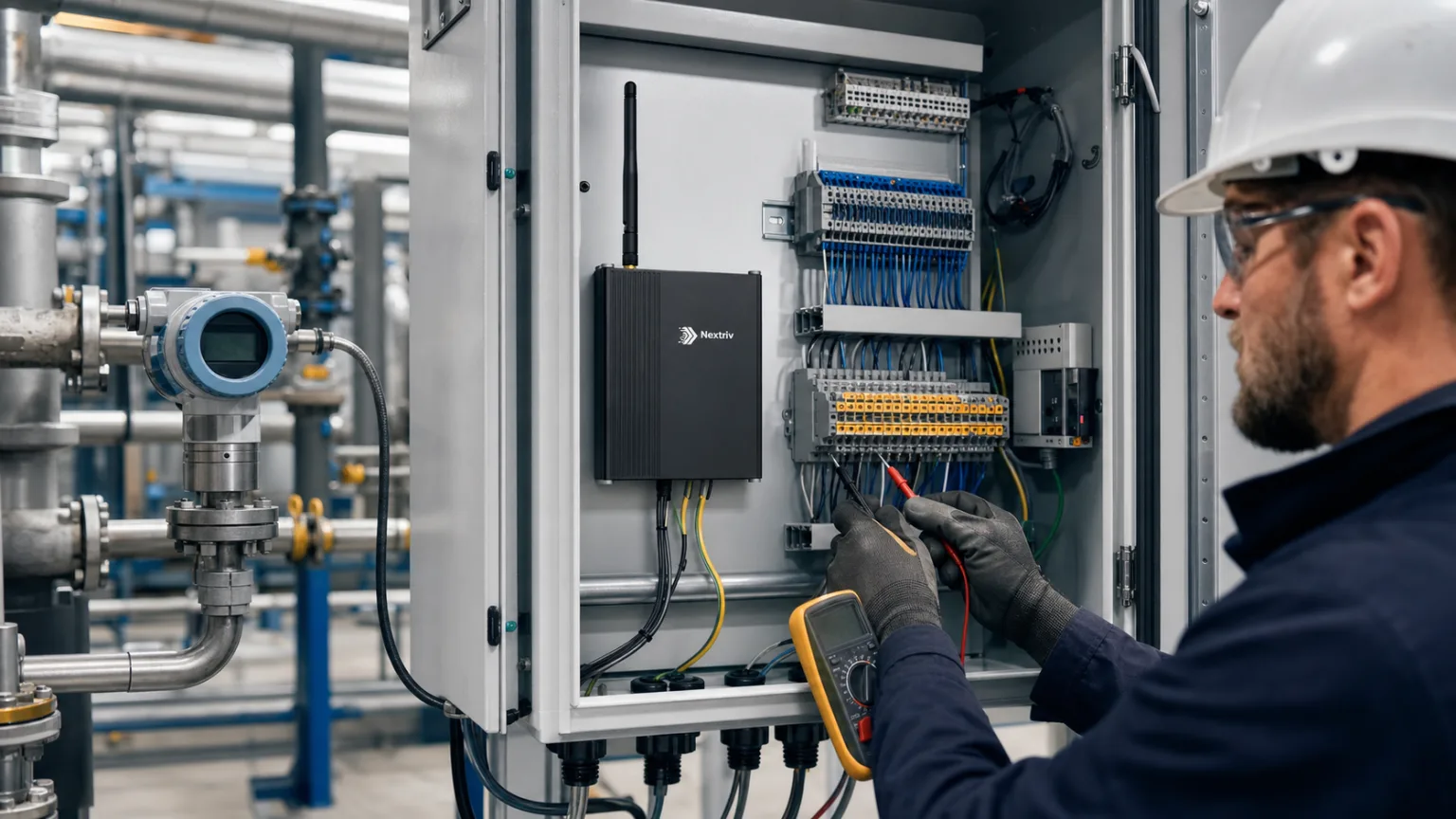
In many plants, the most valuable sensor is neither new nor wireless. It is the pressure transmitter on a pipe, the level probe in a tank, or the humidity transmitter in a dryer that has been feeding a 4–20 mA signal to a local indicator for years. The measurement works, but it stops at the control-cabinet door: there is no history, remote alarm, or shared dashboard for several sites. Replacing the entire measurement chain is not always necessary. The existing signal can be digitised and included in online monitoring — provided that its scale, power supply, and loop diagnostics are understood correctly.
What a 4–20 mA signal actually carries
A current loop transmits neither a parameter name nor a unit. It carries one current value, which the receiver must convert using the range stated in the transmitter documentation. In the common arrangement, 4 mA represents the lower end of the range and 20 mA the upper end. For a 0–10 bar pressure transmitter, that gives:
- 4 mA = 0 bar,
- 12 mA = 5 bar,
- 20 mA = 10 bar.
The linear conversion is simple, yet one incorrect configuration field can reverse the scale or turn 6 bar into 60. Commissioning therefore starts with four numbers: the electrical minimum and maximum and their corresponding physical minimum and maximum. The channel name, unit, and direction of the relationship matter as well — not every transmitter is necessarily configured with an increasing range.
Four milliamps is known as a “live zero.” A valid process zero still produces current, so a broken wire or dead transmitter may return a signal clearly below the working band. That is valuable diagnostic information, but not a universal recipe. Exact fault currents depend on the transmitter, its configuration, and the adopted convention. The monitoring system should distinguish a measurement-path fault from a valid minimum value, while the diagnostic limits must come from the device documentation.
Why industry still relies on this standard
Current transmission performs well over long cables and in the electrically noisy environment of plants, pumping stations, and mechanical rooms. Changing cable resistance affects the required voltage headroom, but in a correctly designed loop the transmitter maintains the requested current. A two-wire transmitter can also draw its power from the same pair that carries the measurement.
This does not make the loop immune to every design error. Insufficient supply voltage, excessive cable and receiver resistance, ground loops, or connecting an active output to an active input can still cause incorrect readings or damage. Before wiring, determine whether the transmitter uses two, three, or four wires, which component powers the loop, and whether the input is isolated. In an existing installation, also verify that adding another receiver will not exceed the available voltage budget.
From transmitter to cloud history
The complete path has five elements: the transmitter, a powered loop, an analogue input, connectivity to the platform, and an alarm rule. Each answers a different question. The transmitter measures the process, the input converts current into a number, the platform stores and presents the result, and the rule compares it with operating limits.
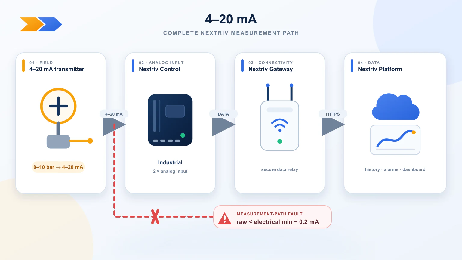
Nextriv Control Industrial provides two 4–20 mA inputs. For each channel, the platform maps the electrical range to engineering units. Once full scaling is configured, the system automatically classifies a raw signal more than 0.2 mA below the electrical minimum as a measurement-path fault; the fault band is not configured separately. The result appears on the same dashboards and in the same history as measurements from wireless sensors. Four thresholds can cover it: warning and critical levels on both the low and high sides.
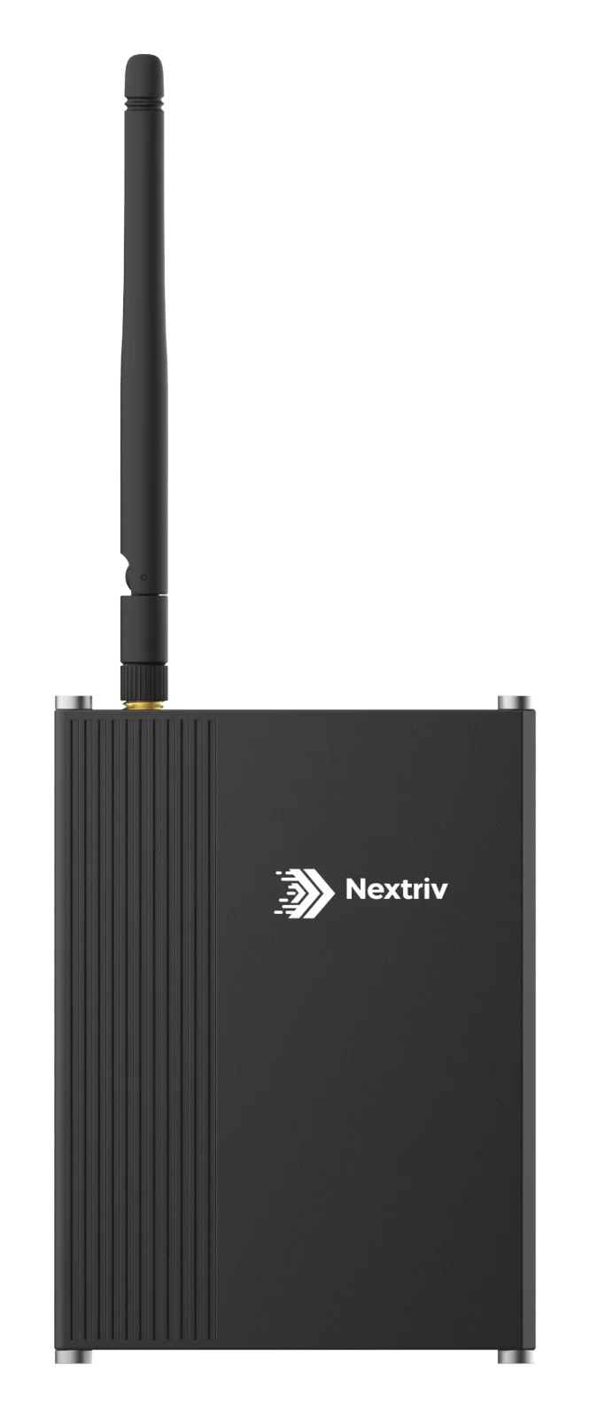
The controller also supports local rules that run without a cloud connection. This is useful for ordinary site automation, but it does not turn the complete arrangement into a certified safety function. Remote monitoring, quality alarms, and machine protective controls are three distinct layers whose requirements should be defined separately.
Configuration that preserves the process meaning
A practical commissioning sequence has seven steps.
- Identify the transmitter. Record its model in the technical documentation, together with its physical range, supply arrangement, permitted load, and fault behaviour.
- Check the loop diagram. Confirm polarity, the power source, common ground or isolation, and every receiver already connected in series.
- Give the channel meaning. “AI1” tells an operator nothing. “Pump P-2 discharge pressure [bar]” identifies the variable, asset, and unit.
- Enter the scaling. Map 4–20 mA to the range on the transmitter nameplate or data sheet, not to a value remembered by a technician.
- Test at least two points. Ideally, force a value near the bottom and top of the range or use a loop calibrator. One-point comparison will not reveal a scale-slope error.
- Test a wire fault. A controlled disconnection during acceptance confirms whether the system shows a path fault rather than a false zero. A competent person performs the test only when the process permits it.
- Set thresholds with the process owner. A technological limit, warning level, and critical threshold do not follow from the 4–20 mA range. They follow from equipment instructions, the risk assessment, and the product's permitted conditions.
As with PT100 process temperature monitoring, calibrating the transmitter alone does not automatically test the complete chain. If decisions depend on the value shown by the platform, periodically verify the path from an applied reference through the analogue input to the record and alarm. Our guide to sensor calibration explains how to interpret the resulting evidence.
Three common applications
Pressure and flow. An existing transmitter on compressed air, process water, or a filter can supply a trend chart. A slow pressure drop after hours can guide a leak investigation, while a growing differential across a filter can inform maintenance planning. The correlation alone is not a diagnosis; it needs the operating context of pumps and valves.
Tank level. A hydrostatic 4–20 mA transmitter can be scaled to metres or percentage full. Converting that value to litres also requires the tank geometry; a vessel with an irregular cross-section must not be assumed to have a linear volume curve.
Machine parameters. Load current, vibration, temperature from a local transmitter, or valve position can share one maintenance dashboard. Combined with remote pulse counters, the data can relate process condition to cycle count, while API and webhooks can pass an alarm to a maintenance-management system.
Where monitoring ends
Connecting a transmitter to a platform does not change the classification of either the transmitter or the installation. If the circuit operates in a hazardous area, performs a safety function, or is subject to regulated qualification, the design must meet the relevant equipment and documentation requirements. Nextriv Control Industrial should not be represented as a SIL or ATEX component, or as an emergency machine safeguard, without a separate assessment and documented design. A competent person should carry out control-cabinet work and any intervention in an operating loop.
For ordinary telemetry, the benefit is very concrete: a serviceable transmitter stays in place but gains history, a readable engineering value, thresholds, and multi-site access. This allows a manufacturing monitoring project to begin with data the plant already owns instead of replacing every field sensor.


