Cleanroom Differential Pressure — Monitoring Under EU GMP Annex 1
How to monitor cleanroom differential pressure: cascades, the 10 Pa Annex 1 guidance value, transmitter selection, alarms and qualification.
Zespół Nextriv4 min read
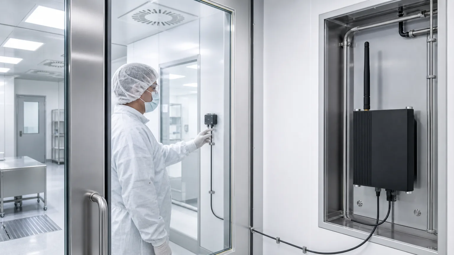
The pressure difference between cleanrooms is small, but its purpose is significant: it helps maintain airflow from the cleaner zone towards the less clean one. If a fan stops, a door remains open, or a filter increasingly restricts flow, the cascade may weaken or reverse before an operator notices. That is why a gauge read once per shift can be insufficient at critical points. Continuous monitoring provides not only the current value but also the timing, course, and documented response to a deviation.
Pressure alone, however, proves neither cleanliness nor sterility. It is a parameter that affects room performance, not a substitute for particle classification, airflow tests, HVAC qualification, or the contamination control strategy. A sound design begins with this boundary.
What EU GMP Annex 1 actually says
Annex 1 of the EU GMP guidelines applies to the manufacture of sterile medicinal products. Fully applicable since 25 August 2024, it requires critical pressure differences to be continuously monitored and recorded. A warning system must immediately indicate a failure of the air supply or a reduction below established limits. Other pressure differences may be monitored at regular intervals, depending on risk.
The often-quoted 10 Pa is given by Annex 1 as a guidance value for the minimum pressure differential between adjacent rooms of different grades. It is not a universal threshold for every cleanroom, airlock, and laboratory. The correct operating band follows from the design, qualification, and contamination control strategy. In containment applications, the airflow direction may deliberately be reversed to protect the surroundings from a hazardous substance. Mechanically applying “always +10 Pa” could make such a facility less safe.
Annex 1 allows an alarm delay only when it has been assessed and justified within the contamination control strategy. This is not permission to smooth away inconvenient events. Door-opening time, the natural response of an airlock, and process risk must be understood during qualification, then used to document which departures require a warning and which require a critical response.
Annex 1 and ISO 14644 answer different questions
The ISO 14644 family covers cleanrooms in many sectors, not only pharmaceuticals. ISO 14644-2 sets minimum requirements for a monitoring plan based on parameters that measure or affect airborne particle concentration, while ISO 14644-3 describes test methods for room performance. EU GMP Annex 1 places monitoring within the specific framework of sterile medicinal-product manufacture and a contamination control strategy.
In practice, the standard, regulatory expectations, HVAC design, and site procedures need to form one system. We explore the boundary between classification and operational supervision in our article on cleanroom monitoring under ISO 14644 and in the guide to GxP monitoring validation.
The measurement chain begins on both sides of the wall
A differential-pressure transmitter compares two points: the high- and low-pressure sides. The pressure taps, impulse tubing, tube routing, and mounting arrangement are as much part of the chain as the electronics. A kinked tube, leak, condensation, or swapped ports will reverse or distort the result even when the transmitter itself is healthy.
Differences of a few or a few dozen pascals require an external low-range transmitter selected for the actual operating band and for any required indication of both positive and negative values. Choosing a very wide range “for safety” reduces useful resolution. Accuracy near the bottom of the scale, zero stability, response time, calibration options, and overpressure behaviour also matter.
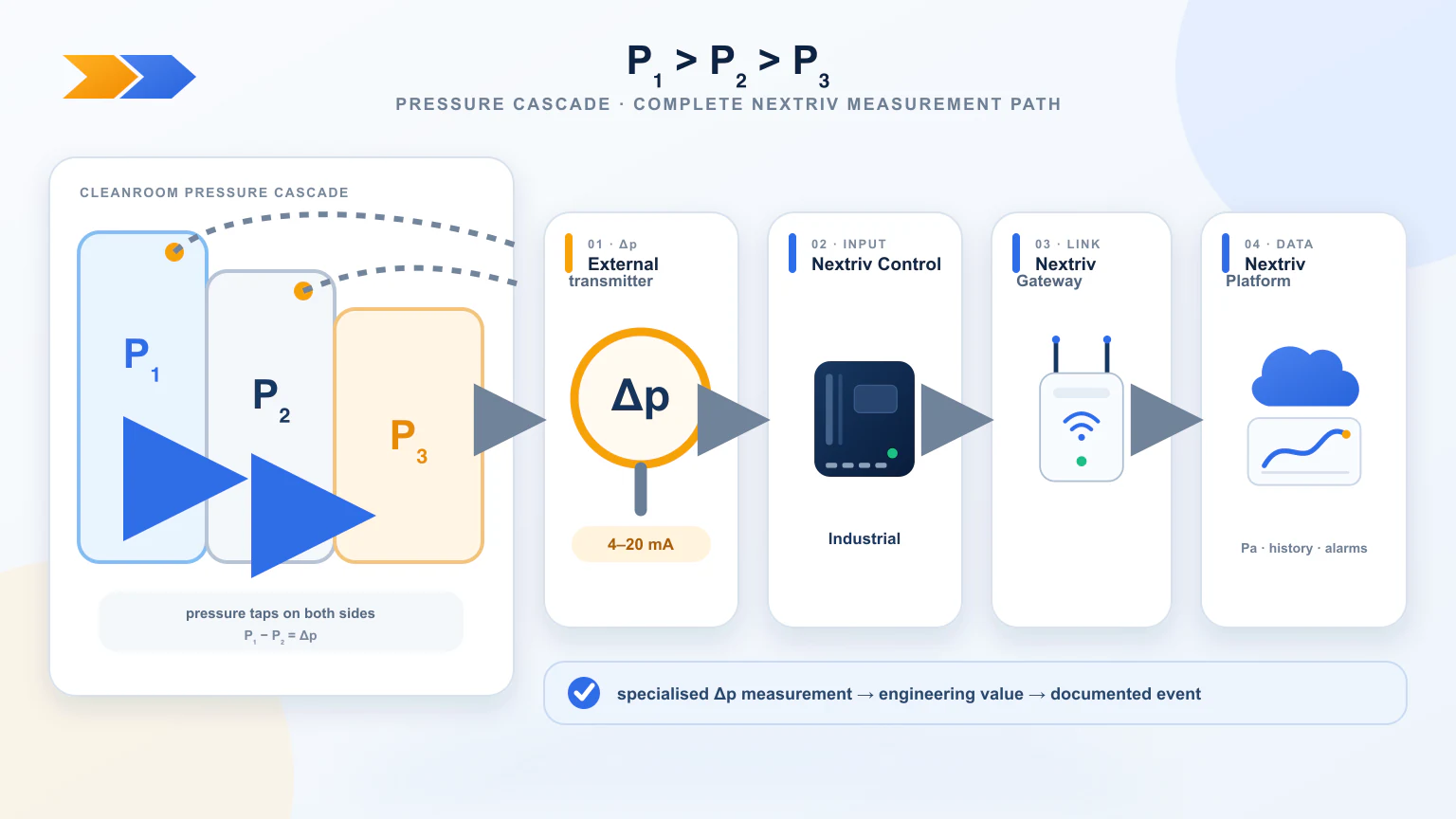
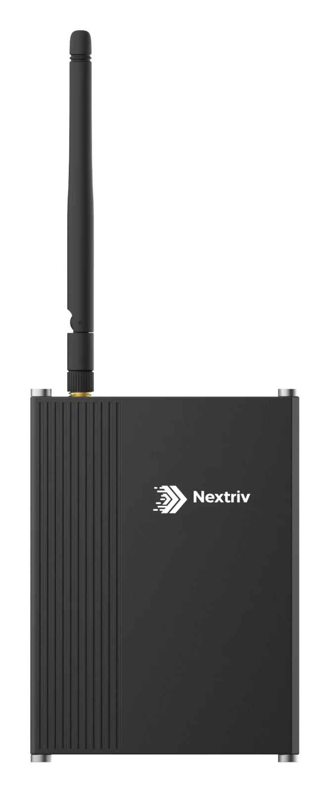
A transmitter with a 4–20 mA output can be connected to Nextriv Control Industrial. The controller scales the signal into pascals according to the device range, records its history, and supports two low and two high thresholds. This architecture uses a specialised sensing element for small pressure differences and the platform for visualisation, alarms, and documentation. Our guide to connecting a 4–20 mA sensor explains scaling and loop diagnostics in more detail.
Channel naming should remove any ambiguity about the sign. Instead of “DP-03,” use “Room B relative to corridor [Pa]” and explicitly define a positive value as higher pressure in Room B. Label the pressure taps and tubes with the same names. A tube swap during service then becomes more than an inverted line on a chart: the operator can immediately understand which way the cascade has moved. Where several room boundaries are monitored, every chain needs an unambiguous identifier, physical location, and reference in the qualification documentation.
Qualification, not a template, defines the thresholds
First establish the normal operating band in different states: at rest, during routine operation, while staff pass through, during material transfer, and through process-equipment cycles. Thresholds follow only after this work. A typical arrangement may include:
- a low warning where the cascade is weakening but remains within an accepted response zone,
- a low critical alarm at loss of the qualified minimum,
- high thresholds if excessive pressure makes doors difficult to operate or indicates a control problem,
- a separate rule for failure of the measurement path itself.
A warning value must not masquerade as a regulatory limit. It is an early-response tool chosen by the site. The critical limit and required actions need to be consistent with qualification, the risk assessment, and the deviation procedure. If a process needs an alarm delay or complex logic involving door state, that logic must be separately engineered, validated, and justified — a basic threshold cannot be assumed to understand airlock context.
What an event record should contain
A chart alone is not enough. A useful record includes the start time, minimum or maximum value, duration, affected rooms, operator acknowledgement, actions taken, and time of recovery. Comparing pressure with door status, fan operation, or an HVAC alarm can shorten the investigation, although correlation does not replace root-cause analysis.
Common scenarios include:
- both airlock doors being open or a failed door closer,
- loss of supply or extract air,
- gradual filter loading,
- a changed air balance after construction or service,
- transmitter zero drift,
- a leaking or blocked impulse tube.
An alarm should lead to a procedure, not merely a message. The operator acknowledges the event, protects the process, checks doors and HVAC, assesses potential product impact, and quality personnel decide what follows. Alarm history and comments help document this sequence, just as they do in other laboratory monitoring systems.
Monitoring does not replace qualification
Before use, the chain must be commissioned and qualified: verify polarity, indication against a reference, 4–20 mA scaling, alarms, signal interruption, timestamps, and recipient response. Periodic calibration follows, as does reassessment after a change to HVAC, room layout, the transmitter, or alarm logic. Our temperature sensor calibration guide explains the useful distinction between calibration and a quality decision; the same metrological logic applies to pressure.
Properly designed monitoring provides early warning and a reliable history of the pressure cascade. It does not “certify the cleanroom” or prove sterility. It is one controlled component of a larger system, showing when conditions departed from the qualified state and how the organisation responded.